Designing a solar array is not only about fitting the maximum number of panels onto a site. Row spacing directly affects energy production, maintenance access, construction costs, and long-term reliability. When panels are placed too closely, one row can cast shadows across the next, especially during low winter sun. Even a narrow shadow can reduce the output of several modules.
This guide explains how to calculate the distance between solar rows to avoid shading using practical geometry and site-specific solar data. The process considers panel height, tilt angle, row orientation, latitude, and the sun’s winter elevation. A typical calculation begins by finding the vertical height difference between the front and rear edges of a tilted panel. That height is then compared with the sun angle during the critical design period. Small errors matter.
In real projects, experienced designers rarely trust one formula alone. They review local terrain, nearby trees, roof equipment, wind requirements, and access paths. Simulation tools can test hourly shading throughout the year, while field measurements help confirm assumptions. Yet no method is perfect. Weather, uneven ground, and installation tolerances can change the final result. A reliable design therefore includes a sensible clearance margin rather than relying on the smallest possible spacing. This approach may sacrifice a little land efficiency, but it can protect annual yield and simplify future maintenance.
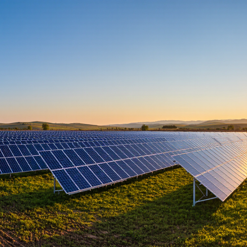
Solar row spacing is the horizontal distance between corresponding points on two neighboring photovoltaic rows. It is not simply the gap between panel edges. The measurement usually runs from the front edge of one row to the front edge of the next. This distance controls how much sunlight reaches the lower part of each array.
Proper spacing prevents one row from shading another during critical sunlight hours. Designers examine the sun’s altitude, panel tilt, row height, and site latitude. Winter usually creates the longest shadows, so it often determines the minimum spacing. A simple estimate uses row height divided by the tangent of the sun’s chosen altitude angle. For example, a raised edge one meter high needs more separation when the winter sun sits low. Local terrain can change the result.
Small errors matter. A few extra centimeters may protect morning production. Too much spacing, however, wastes usable land and increases cable runs. I have found that drawings can look accurate while ignoring drainage channels, uneven ground, or nearby trees. That shortcut is risky. Check shadows at several hours, not only at noon. A computer model helps, but field measurements remain valuable. Record the lowest winter sun angle and compare it with the project’s energy goals. The best spacing is site-specific, practical, and open to revision when real conditions challenge the first design.
Solar row spacing is the horizontal distance from one panel row to the next. To reduce inter-row shading, the minimum pitch can be estimated from the panel row height and the sun’s altitude: minimum spacing = row height ÷ tan(solar altitude).
This chart uses a 2.0 m row height and the approximate solar altitude at 9:00 solar time near the winter solstice. Higher latitudes have a lower winter sun angle, so they require greater spacing to preserve sunlight between rows.
How to Calculate Solar Row Spacing to Avoid Shading?
Solar row spacing depends on more than panel dimensions. Site conditions often control the real shadow pattern. Latitude changes the sun’s height across the year. In winter, the sun stays lower and creates longer shadows. Solar elevation can be calculated for the design date, often the winter solstice. A basic estimate uses shadow length = obstacle height ÷ tan(solar elevation). The obstacle may be a panel’s upper edge, nearby trees, or a raised structure.
Check the site’s orientation and slope before selecting a spacing value. A south-facing array usually needs different spacing from an east-west layout. Uneven ground can make one row higher than expected. That small difference can extend shadows across the next row. Panel tilt also matters because steeper panels increase the effective row height. Measure nearby buildings, fences, poles, and vegetation at their actual heights. Trees are especially difficult because they grow and change shape. Winter is different.
Local weather and energy goals affect the acceptable shade level. Some projects avoid shading between 9 a.m. and 3 p.m., while others protect a wider production window. Use a sun-path study or professional simulation for accurate results. I once treated a flat site as uniform and underestimated a shallow ridge. The calculation looked reasonable, but the layout needed revision. Leave practical access space for cleaning, repairs, drainage, and snow movement. A slightly wider gap may produce better long-term results than the tightest theoretical design.
The solar elevation angle is the key measurement. It shows how high the sun stands above the horizon.
Here, α is solar elevation, φ is site latitude, δ is solar declination, and H is the solar hour angle. At solar noon, H equals zero. At 9 a.m. solar time, H is minus 45 degrees. At 3 p.m., it is plus 45 degrees.
For a site at 35 degrees north on the winter solstice, the 9 a.m. elevation is about 18 degrees. The low angle is easy to underestimate.
Divide the height difference between rows by tan(α). If the rear edge rises 1.5 meters above the ground, spacing at 18 degrees is about 4.6 meters.
Measure the height difference carefully, not just the panel height. Tilt, uneven ground, and support structures can change the shadow length. Use true solar time, not simply the clock time. Time zones and daylight-saving adjustments can shift the result.
Then I test the morning and afternoon periods when energy demand matters most. A small safety margin helps cover terrain errors and cloudy-day uncertainty.
My early layouts were sometimes too optimistic. Local surveying and a second calculation are worth the extra effort.
Solar row spacing determines whether one panel row shades another during low winter sun. The minimum distance depends on panel length, tilt angle, site latitude, and the sun’s elevation. A practical calculation begins with the panel’s vertical rise, measured from its lower edge to its upper edge.
Use this simple relationship: shadow length equals vertical rise divided by the tangent of the sun’s elevation angle. For example, a panel with a 1.7-meter slope and a 30-degree tilt rises about 0.85 meters. At a 20-degree winter sun angle, its shadow may extend about 2.3 meters. Add the panel’s horizontal projection, about 1.47 meters, and the row pitch should approach 3.8 meters. Keep extra clearance for uneven ground, installation tolerances, and maintenance access.
That number is only a starting point. The sun’s direction also matters, especially on sites with east-west layouts or nearby obstacles. I once relied on a noon calculation and underestimated morning shading. It looked acceptable on paper. It was not. Check the design at the desired winter shading period, such as 9 a.m. to 3 p.m., using local solar data. A digital sun-path tool or a physical site survey can reveal errors that formulas miss. Recheck the result after confirming the actual panel dimensions and mounting height. Small changes matter.
| Design Item | Value or Formula | Purpose |
|---|---|---|
| Reference panel length along slope | 2.278 m | Representative dimension for a modern large-format photovoltaic module installed in portrait orientation. |
| Reference panel width | 1.134 m | Useful for estimating the row width when modules are installed side by side. |
| Panel tilt angle, β | 25°, 30°, or 35° | The tilt changes both the panel ground projection and the height that creates a shadow. |
| Solar altitude, α | Sun angle above the horizon | A lower winter solar altitude creates a longer shadow and requires greater row spacing. |
| Recommended design period | Winter solstice | This is generally the most critical period because the sun reaches its lowest annual elevation. |
| Reference time window | 9:00 a.m. to 3:00 p.m. solar time | The table uses the lower solar altitude at the edge of this six-hour window. |
| Site Latitude | Approx. Solar Altitude at 9:00 Solar Time | Panel Tilt | Panel Ground Projection | Shadow Length | Minimum Row Pitch |
|---|---|---|---|---|---|
| 25° N | 24.8° | 25° | 2.06 m | 2.08 m | 4.15 m |
| 35° N | 17.1° | 30° | 1.97 m | 3.49 m | 5.46 m |
| 45° N | 10.3° | 35° | 1.87 m | 6.12 m | 7.99 m |
| 55° N | 2.8° | 35° | 1.87 m | 38.25 m | 40.12 m |
| Panel Tilt | Ground Projection | Panel Height Creating Shadow | Shadow Length at 17.1° Solar Altitude | Minimum Row Pitch |
|---|---|---|---|---|
| 20° | 2.14 m | 0.78 m | 2.53 m | 4.67 m |
| 25° | 2.06 m | 0.96 m | 3.12 m | 5.19 m |
| 30° | 1.97 m | 1.14 m | 3.49 m | 5.46 m |
| 35° | 1.87 m | 1.31 m | 4.25 m | 6.12 m |
A row-spacing calculation is only a starting point. Verify the layout through seasonal shading checks, because the sun’s path changes sharply across the year. Test the winter solstice, both equinoxes, and a representative summer date. Winter usually creates the longest shadows and the greatest risk of production loss.
Build a site model using each row’s elevation, panel height, slope, and nearby obstacles. Include fences, trees, buildings, and future vegetation growth. Check shadow movement at hourly intervals, not only at solar noon. A row can appear clear at midday but lose sunlight during the morning and afternoon. Pay close attention to the first and last operating hours. These periods often reveal overlooked shading.
Compare the predicted shaded area with the project’s energy target. A useful check is to review the lowest winter sun angles and measure whether one row shades the next. Leave a practical margin for uneven ground, installation tolerances, and changing surroundings. I have found that a perfectly aligned digital model can still be misleading. Small terrain errors matter. Weather data also varies between sites, so avoid treating one simulation as absolute proof. Recheck the design after field surveying, and document the date, time, sun position, and affected rows. This record makes later adjustments more reliable.
It is the horizontal distance between matching points on neighboring photovoltaic rows. Measure front edge to front edge. It is not only the visible gap between panel edges.
Adequate spacing keeps one row’s shadow away from the lower part of another row. This protects sunlight during important production hours. Small spacing errors can matter.
Designers consider sun elevation, panel tilt, row height, site latitude, and ground slope. Winter often controls the minimum distance. The sun sits lower then.
Divide the height difference between rows by the tangent of the solar elevation angle. The basic formula is: spacing = height difference ÷ tan(α).
Use sin(α) = sin(φ)sin(δ) + cos(φ)cos(δ)cos(H). Here, α is solar elevation, φ is latitude, δ is declination, and H is the hour angle. Use true solar time.
Check the winter solstice, both equinoxes, and a representative summer date. Review morning, noon, and afternoon conditions. Noon alone can mislead.
Include row elevations, panel height, tilt, slopes, fences, trees, buildings, and drainage channels. Consider future vegetation growth. Uneven ground is easy to overlook.
No. A model is useful, but field measurements remain necessary. Survey actual terrain and compare a second calculation. My early layouts were sometimes too optimistic.
A practical margin can cover terrain errors and installation tolerances. Too much spacing wastes land and lengthens cable routes. The balance is site-specific.
Record the date, time, sun position, affected rows, and shaded areas. Recheck the layout when real conditions differ from the model. One simulation is not absolute proof.
Solar row spacing is the horizontal distance between adjacent rows of photovoltaic panels, and choosing it correctly helps prevent one row from casting a shadow on another. To determine the required spacing, first evaluate site conditions such as latitude, terrain slope, panel tilt, panel height, orientation, and any nearby structures or vegetation. These factors influence the length and direction of shadows throughout the day.
A practical method for how to calculate the distance between solar rows to avoid shading is to identify the solar elevation angle during critical periods, especially winter mornings and afternoons when the sun is lowest. Using the panel height and the tangent of this solar angle, estimate the shadow length and set the row-to-row distance at least equal to that value, with an additional safety margin if needed. Finally, verify the layout through seasonal shading checks at different times of day, then adjust the spacing to balance energy production, land use, maintenance access, and installation requirements.

Ran Solar