A solar mounting system is more than rails beneath panels. Its metal parts can become energized if insulation fails, a conductor loosens, or equipment suffers damage. Proper grounding creates a dependable path for fault current and helps protective devices respond. It also depends on sound bonding between compatible components, not simply attaching one wire to a rail.
PV educator John Wiles has emphasized a practical principle in his solar safety guidance: grounding connections must provide a continuous, reliable path for fault current. That principle shapes how to ground a solar mounting system properly. Use grounding hardware suited to the module and racking manufacturer’s instructions, and check that contact surfaces are clean and secure. Small parts matter. A neat-looking connection can still be electrically poor, especially where coatings, corrosion, or mismatched hardware interrupt metal-to-metal contact. The system’s grounding conductor and bonding points should be inspected and tested with suitable methods by a qualified solar professional. Do not assume rails bond every module automatically; confirm the listed design and installation details. That assumption is easy to make. It deserves a second look. This introduction sets up the key questions: which parts need bonding, how continuity is verified, and what site conditions can weaken a connection over time. The exact approach depends on the equipment and applicable local requirements, so generic diagrams should never replace project-specific instructions.
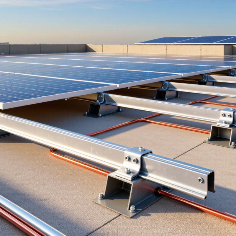
Grounding gives fault current a controlled path away from people and equipment. In a solar mounting system, bonding connects module frames, rails, clamps, and racking electrically. This creates one continuous conductive network. It is not simply a wire driven into soil.
A properly installed equipment grounding conductor connects the mounting structure to the building’s grounding system. It should remain continuous through every section, including rail splices and separate mounting rows. Approved bonding hardware must bite through coatings and maintain metal-to-metal contact. Tightening matters, but overtightening can damage parts. That detail is easy to miss.
I have seen installations that looked neat but failed a continuity check. Dust, paint, loose fasteners, or corrosion can interrupt the path. A technician should inspect connections, verify torque, and test electrical continuity with suitable equipment. The test should cover the full array, not one convenient section. Do not rely on appearance alone.
Grounding requirements vary by location, system design, and electrical rules. A qualified professional should confirm conductor sizing, grounding electrode connections, and required disconnects. Local authority requirements also matter. Solar modules may produce dangerous voltage during daylight, even when the inverter is off. Treat every conductor as energized until testing proves otherwise. Mistakes happen, especially during rushed rooftop work. Careful documentation helps reveal them.
What Is Proper Grounding for a Solar Mounting System?
Why Electrical Bonding and Grounding Are Necessary
A solar mounting system needs more than strong rails and secure bolts. Its metal modules, rails, clamps, and support structure should form a continuous electrical path to ground. Electrical bonding connects these parts together. Grounding then provides a controlled path for fault current, helping protective devices respond before exposed metal becomes dangerous.
In field inspections, small details often cause the largest concerns. A painted connection surface may interrupt continuity. A loose bonding washer may fail after repeated thermal movement. Corrosion can also weaken a connection that looked reliable during installation. Use listed bonding hardware, correctly sized conductors, and torque values specified by the manufacturer. Then test continuity between the array structure and the grounding point.
The grounding electrode system must match the building’s electrical design and local requirements. A qualified electrician should verify conductor routing, connection points, and overcurrent protection. Do not assume that a grounded inverter automatically grounds every metal component. It may not.
Measure it properly.
A visual inspection is useful, but insufficient. Record test results, inspect exposed connections, and revisit them after severe weather or maintenance work. I have seen otherwise careful installations miss one isolated rail. That mistake is easy to overlook and difficult to justify later. Good grounding depends on consistent workmanship, suitable materials, and honest verification.
A solar mounting system needs a continuous, low-resistance grounding path. That path usually begins at the module frame, where approved bonding hardware connects the frame to the mounting rail. Bonding washers or serrated clamps must penetrate anodized surfaces when required. Ordinary washers may look secure, but they may not provide reliable electrical contact.
The rail system continues through rail splices, bonding jumpers, and equipment grounding conductors. Each splice needs compatible hardware and correct torque. A loose connection can interrupt the path, even when the array appears mechanically solid. From the rails, the grounding conductor typically travels through junction boxes, disconnects, and inverters before reaching the building grounding system or grounding electrode system. Metal conduits and enclosures may also form part of the path, but only when their fittings are listed and properly installed.
Field experience shows that small details cause many failures. Paint, dirt, corrosion, and over-tightened lugs deserve close inspection. Installers should verify continuity with suitable test equipment and record torque values during commissioning. I would not assume that every metal rail is bonded automatically. Design documents, local electrical rules, and equipment instructions must confirm each connection. Conditions change after installation, too; a later roof repair can disturb a bonding point. That possibility needs consideration.
Which components form the grounding path?
The chart shows the typical order of the equipment grounding path, not electrical measurements. Bonding hardware and conductor connections must be suitable for the equipment and installed according to applicable electrical codes and manufacturer instructions.
Proper grounding gives fault current a low-resistance path back to the electrical source. This path helps protective devices disconnect power quickly. For a roof-mounted system, the mounting rails, module frames, and equipment grounding conductor must work as one connected system. Local electrical codes and the equipment manufacturer’s instructions control the final installation.
Mounting rails are bonded with listed bonding hardware, grounding clips, or approved jumpers. These parts must make reliable metal-to-metal contact. Anodized coatings can interrupt continuity when ordinary fasteners are used. Installers should follow the hardware instructions and verify contact at every rail connection. When rails are separated, a bonding jumper may be necessary. A loose connection can look acceptable but fail during a fault.
Solar panels are bonded through approved clamps or grounding lugs at their marked grounding points. The clamp must contact the module frame correctly without damaging it. A continuous grounding conductor then connects the array to the building grounding system. Never assume a rail is grounded because it touches a roof bracket. Testing with a suitable meter can reveal hidden resistance, reversed connections, or an open bond. In real installations, rushed checks are a weak point. Dust, corrosion, and over-tightened hardware deserve attention. Good workmanship also records test results, hardware locations, and any later changes. Some systems still leave uncertainty when components come from different instructions, so the installer should pause and verify compatibility before energizing the array.
Grounding is not just a wire attached to a rail. It is a verified electrical path from exposed metal parts to the system’s grounding point. Check the approved drawings, equipment instructions, and locally adopted electrical code before installation. In the United States, NEC Article 690 addresses photovoltaic systems; Article 250 covers grounding and bonding. Requirements vary by jurisdiction. Ask the local authority having jurisdiction which code edition and inspection rules apply.
Inspect each module frame, mounting rail, splice, and bonding connection for compatible hardware and clean metal contact. A painted or anodized surface may interrupt continuity unless the listed fitting is designed to pierce it. Use the specified torque, then document connections and test electrical continuity with suitable equipment. A visual check alone is not enough. UL 2703 evaluates mounting systems for bonding and grounding performance, while NREL’s Best Practices for Operation and Maintenance of Photovoltaic and Energy Storage Systems recommends documented inspection procedures. The IEA PVPS Snapshot of Global PV Markets 2024 reports more than 1.6 terawatts of cumulative solar capacity worldwide at the end of 2023—a reminder that consistent verification matters across a rapidly expanding industry. Still, paperwork can miss a loose splice. Recheck after installation, especially where rails meet.
Grounding creates a controlled path for fault current. Bonding connects module frames, rails, clamps, and supports. Together, they form one conductive network. It is not merely a wire buried in soil.
Bonding keeps exposed metal parts electrically connected. Grounding helps protective devices respond to faults. Without continuity, metal surfaces may become hazardous. Strong bolts alone are not enough.
Bond module frames, mounting rails, rail splices, clamps, and support structures. Separate mounting rows may need individual connections. Every section should connect to the grounding system. One isolated rail can undermine the whole path.
Yes, paint, dust, oxidation, and corrosion can block metal contact. Use approved hardware designed for the surface. Clean contact areas when required. A neat connection may still fail testing.
Inspect every connection visually. Then test continuity with suitable electrical equipment. Test from the array structure to the grounding point. Do not test only the easiest section.
Not always. The inverter may not bond every metal component. Confirm conductor routing and connection points separately. This assumption causes avoidable mistakes.
Use correctly sized conductors and compatible bonding hardware. Follow specified torque values carefully. Overtightening can damage fittings or metal parts. Undertightening can loosen during thermal movement.
Requirements vary by location, building design, and system type. Local inspection rules may also differ. A qualified professional should confirm conductor sizing and connections. The paperwork may look complete, but one loose splice can remain.
Recheck them after severe weather, repairs, or maintenance work. Inspect exposed connections for looseness and corrosion. Keep test results and connection records. No checklist is perfect. Rechecking still helps.
Proper grounding in a solar mounting system creates a safe, continuous path for fault current and helps protect people, equipment, and the structure from electrical hazards. It is different from simply connecting a system to the earth: grounding establishes a reference and discharge path, while bonding electrically connects exposed metal parts so they remain at the same potential. Both are necessary for reliable protection and safe system operation.
The grounding path commonly includes the panels’ frames, mounting hardware, rails, bonding components, grounding conductors, and the building’s grounding electrode system. Rails and panels are bonded using approved conductive connections that remove paint, coatings, or other insulating barriers where required. To understand how to ground a solar mounting system properly, installers should follow the system design, use compatible materials, inspect every connection, and test electrical continuity. Final verification should confirm that the entire path is continuous, secure, corrosion-resistant, and consistent with applicable electrical codes and local inspection requirements.

Ran Solar